
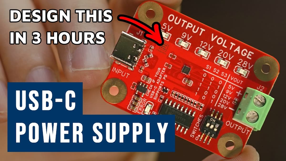
How to Design a USB-C Power Supply (5V–28V) in 3 Hours | Full Tutorial | EasyEDA
The video walks viewers through building a USB‑C power‑supply board that delivers 5 V to 28 V, using only a web browser and EasyEDA’s Pro edition. No local software installation is required; users create a new project, name schematics and PCB files, and set up a professional‑looking title block. Key steps include selecting a 28 V‑rated USB‑PD controller from LCSC, editing its schematic symbol for clearer pin placement, and adding high‑voltage capacitors, TVS diodes, and filtering components. The tutorial emphasizes using a 0.1 mm grid, copying existing net names to avoid errors, and configuring output voltage via three‑position switches with pull‑up resistors on the CFG pins. Notable details: the presenter saves every change, stores a custom symbol in a personal library, and deliberately places unfitted resistors for future experimentation, annotating them with notes. A simple table maps switch settings to output voltages (5 V, 9 V, 12 V, 20 V, 28 V), illustrating how configuration pins control the regulator. The approach demonstrates that a functional, high‑voltage USB‑PD supply can be designed, documented, and ready for PCB fabrication in under three hours, lowering the barrier for hobbyists and small‑team engineers to prototype power solutions quickly.
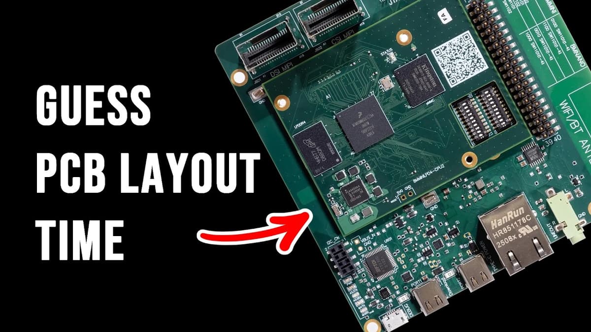
PCB Layout Finished 10x Faster with AI? Here’s How...
The video introduces Quilter, a startup applying artificial intelligence to the PCB layout stage of hardware design, and explains how its founders aim to shrink the traditionally slow layout process. Quilter deliberately avoids LLMs, treating layout as a geometry‑and‑physics problem solved...
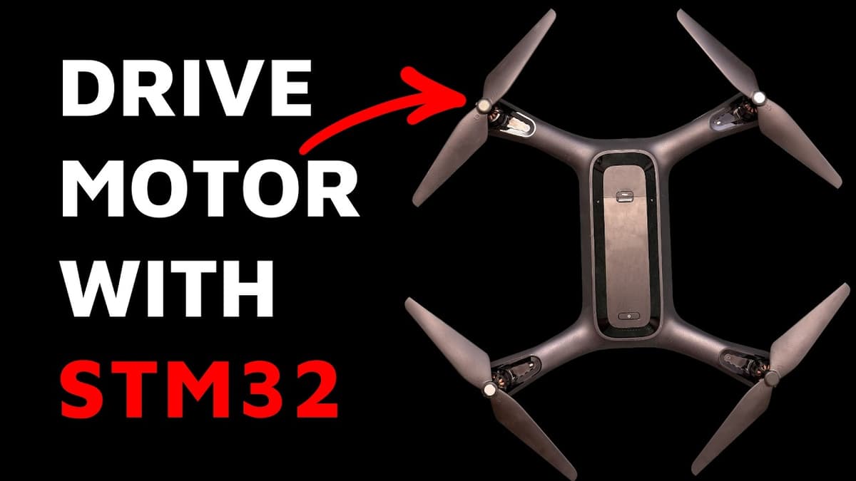
Driving a Motor with STM32 | Quick Tutorial (Drone Example Using GaN Controller)
The video walks viewers through a step‑by‑step tutorial on driving a high‑power agricultural‑drone motor using an STM32 microcontroller paired with an EPC GaN inverter. It demonstrates the complete workflow from hardware setup inside a safety cage to software configuration with...
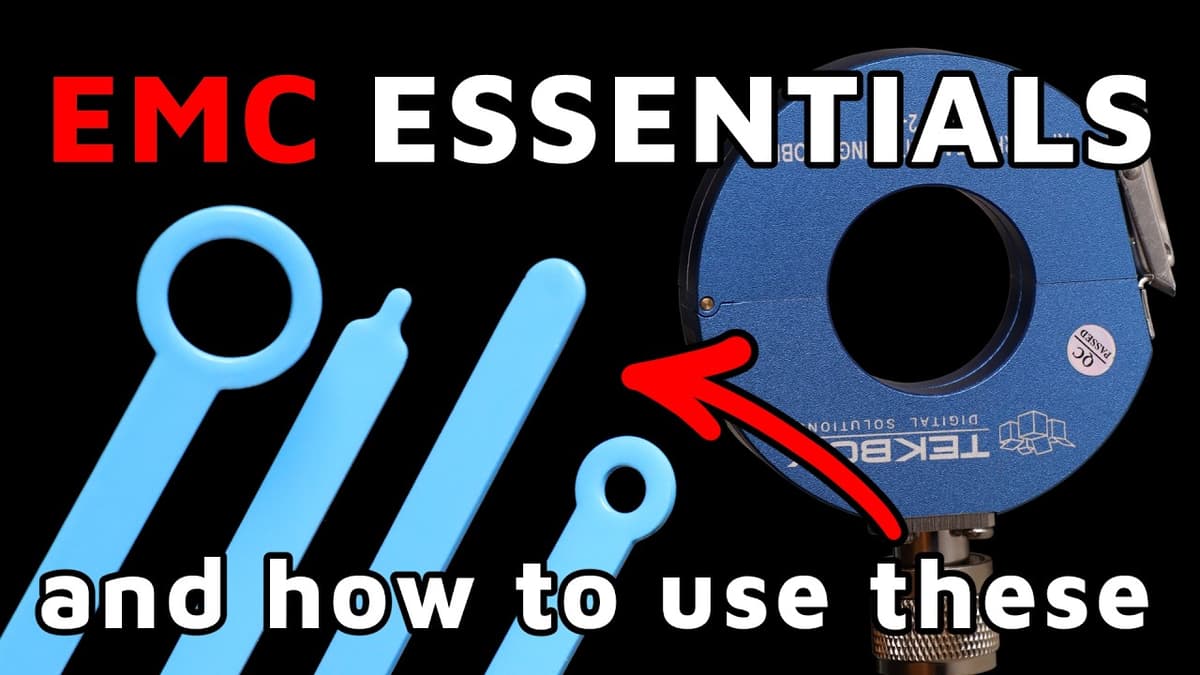
EMC Essentials Explained: Theory & Low-Cost Lab Measurements
The video walks electronic developers through the fundamentals of electromagnetic compatibility (EMC) and demonstrates how to perform practical, low‑cost measurements in a home lab. It emphasizes that EMC testing is not just a regulatory hurdle but also a matter of...

Track Crossing on PCBs - Myth vs Reality
The video tackles a common PCB myth: that routing one signal layer horizontally while the adjacent layer carries vertical traces is inherently safe from interference. The presenters demonstrate that, despite intuition and many signal‑integrity (SI) tools suggesting otherwise, electromagnetic (EM)...

Useful Low-Cost EMC Tools (From $0 to $500)
In the video, the presenter demonstrates how engineers can perform electromagnetic compatibility (EMC) measurements using equipment that costs from zero to about $500, avoiding the six‑figure spectrum analyzers typical of commercial labs. The core setup consists of an inexpensive function generator...
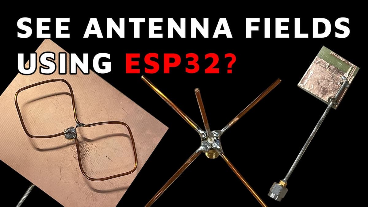
How to Design an Antenna That Actually Works | All Steps Explained
The video walks through practical antenna design from theory to measurement, presented by Quarterwave co-founder Nicola. It explains key RF concepts—S11 reflection coefficient, 50-ohm matching, Smith chart matching techniques, radiation efficiency and directivity—and demonstrates rapid prototyping, simulation, and real-world integration...
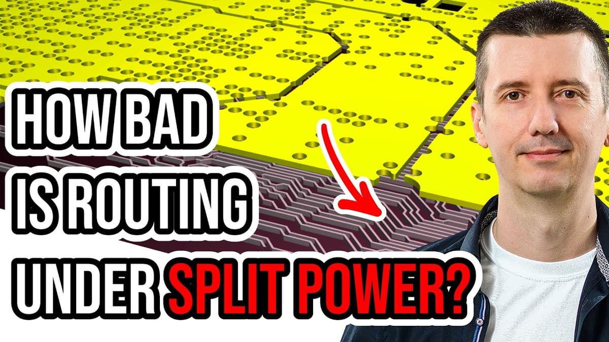
Is This PCB Layer Stackup OK? Solid GND – Signal Layer – Split Planes ???
The video examines how broken or split reference planes in a PCB stack‑up affect electromagnetic fields around high‑speed signal traces. Using Symbur simulations, the presenter compares a symmetric strip‑line with solid ground planes to configurations where one plane contains a...